HOW CENTRAL HEATING WORKS, The history of central heating part 4A – controls
Derek shows you the position needed for a central heating pump and how heating controls work
Link to part 1
Link to part 2
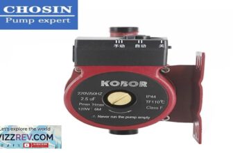
[Music] Tomcat gasps straining and you're about to watch part four of this absolutely amazing fantastic riveting video on the history of central heating now if this is the first video you're watching you've started at the wrong place you need to go back to video one and start from there now if this is the fourth video and you have sat there through one two and three what have you been doing with your life but you must wanting to see part four platforms of controls so let's say join Cheers this is April possible as you can see from the bump we've got to isolation bowels with the pump unions all pumps require isolation valves and funky music as long as your central heating system is correctly installed and properly maintained you could expect your pump to last at least ten years and possibly up to 20 years so the ease of replacement and maintenance if we look actually on the Front's of the pump you could probably just see some letters across the top there okay so what they read is is the UPS 15 – 50 130 so what does that mean well the 50 means the size of the ball coming through here so there could be a 15 or 25 that's the size of the plungers I hear now the fifth day means it's five meters head so well it's at me so you might get a fifty you might get a 60 but 60 would be six meter so that means if we got a cuz this is a 50 we've got a 6 meter piece of pipe coming off the top of there this pump would not be able to pop the water out the top because it's a 5 meter maximum that means this pump can only overcome the weight of 5 meters ok so and the other one the hundred and thirty is the distance from flange to flange okay so that's the from the face of the flange to face of the flange is a hundred and thirty mill so you might be able to see that the 1550 bets there on that one there are a few different types of central heating pumps available there are two speed three-speed and the more modern high efficient pumps which will automatically adjust their speed according to the demand of the central heating system now everybody says grumpus were the ones who invented it they were it was viola we was making pumps way before drum floss I've gone fast the best pumps come faster the most expensive I think so maybe that's why everybody thinks they're the best they've got three speeds on the pumps if this was installed in a combi boiler a lot of the time the speed ease is not is there's been bypass is not there okay but we need to talk about energy pumps in a minute which are in there now so the three speeds for whatever flow rate you wanted coming out of it now if we wish to use install this on a small bore system small ball would be fifteen twenty to twenty eight mill pipe we don't want more than one that meets in a second flowing through there if we're putting out a micro boss so if we've got six eight and ten we wouldn't want the speed of this pump taken more than 1.4 meters a second now the reason we need to keep this speed down is because of noise the faster the water going through the pipe with this monitor the more noise you're gonna get a central heating pump running too fast can cause your electricity bill to soar as well as making night in the system while setting it too slow can mean that your radiators won't heat'll as they should how do we install this pub which way round to install it now if it says in the manufacturer's instructions that we should always be looking at putting the shaft horizontal okay so it should be always be horizontal not dipping down like that not on an angle incorrectly installing a pump will lead to noise and a buildup of air within the pump this will cause the bearings to be damaged and the pump will need replacing now there is a flow arrow on there so you can see the the flow arrow and that tells you which direction but if you can't see that flow arrow the easiest way to check whether which ways the the flow in and which is on the flow out so you got the pump the right way is this bulge no matter what pump is always on the flop so this is where the water flows in and this is where the water flows up now inside this pump there are two berries okay there's a bearing that's up and a bearing the bottom these bearings always need to be lubricated in 1855 radiators were invented in Russia by a Polish bar businessman and the modern-day central heating system was born nearly 30 years later in 1883 the first electric heater was invented by Thomas Edison followed by the first solar water heating system in 1896 so we've got a vent screw here for bleeding okay now on the new pumps a lot the time there is no vents true they are erp pump sell from 2013 we've ATO our energy rated product pumps so the pumps have got to be able to turn the speed down themselves in in you can still get them for traditional systems where I planned less buns you can still get energy pumps biggest problem we have with energy pumps is if you've got a micro ball system on a combi boiler and it's been piped in wrong years ago and you come to put a new boiler on the system there might not be enough energy in the pump to get it all the way to the end – radiator and that's because the the PCB and the boiler is monitoring the flow and return temperatures and if the return temperature starts to creep up see much they will slow the speed of the pump down to try and get the heat out the radiators so it loses its energy to get to the last the last radiator so in that situation we could get away with it by obviously we pipe in the system oh we could put a low loss header in okay and I'll explain low less headers like that's new technology a long lost header is designed to provide hydraulic separation between the boiler and the heating circuits regulating the flow rate and the pressures improving efficiency and performance the long loss header can also be used to allow multiple boilers to be joined together on a heating circuit now let's continue with the pumps let's have a look inside these pumps so this is the grim fast pump taking it apart so it's literally four screws one two three four four screws take them out use an allen key to remove them once you've removed them you can now see it's in two points now because this is a grown fast Punk 85% of the pumps made any head will fit so if you were changing these a lot of the time you don't have to change this path that what is clear is okay this has been taken off the central system which was installed correctly the vent pipe was in the right place and the pump is really clean so this pump was working when it came out it's just that it's been upgraded some are coming this can stay in position no need to undo the unions no need to take it all apart oh we've got to do turn the valves off isolation either side undo the four bolts and we can take it off so how does this work if this is our inlet this is where the water comes in and the water is pumped out if we look on the inside you can see the hole in the middle and that's where the water comes straight can you see the screwdriver comes through that okay yep so that's where it comes through so the water flows through there comes out through the middle then goes through the center of there and it's plumbed out of the impeller this is a centrifugal force pump that means the pump spins the screwdriver through that bit you can now see that's where it comes out so it comes through there down there and that's how it pumps it around now electrical connections the electrical connections on this pump are incredibly easy as you can see from there we've got live neutral and earth and these have little pullback taps so you can see as I'm pulling the live back you can see the little gate opening and that's where you would put the wire there are others where there's a little you can undo the plug screwed screws in and plug it back in obviously while you're going through this grommet here the yellow object in the photograph is a stacked capacitor this holds energy allowing the pump to user energy in start-up now that when you are actually installing this one of the main things we've got to be aware of is this electrical connection doesn't want to be sat at the bottom like that because if we bleep click the bleed screw out the water would run down into the electrical connections and that's not a good idea but because we can move it in four different directions it doesn't matter which way we put this because we can always undo the four screws and move the head into any position we want okay now we can do that with most of the pumps what are out there yeah some of them on you have two screws that the viol Oh some of the nut of the four screws but if you're changing just a head make sure you use the same head the same pump manufacturer otherwise it's not going to work the way it seals is you can just see the little gasket is like a rubber gasket I'm just pulling up there that rubber gasket is really good okay you could probably take this off numerous times put it back on and it would seal so never be afraid of taking the head off even if it's in a combi boiler don't be afraid of taking the head off because that gasket was still sealed even though the bodies in most companies are plastic okay you could still get a good seal on them so that's looking inside a central heating pump the difference between the pump in a combination boiler and the pump on a traditional heating system is normally the size of the impeller now the next thing I want to talk about is motorized vowels motorized valves for Y plan and s4 but now in the videos before I've mentioned why find an S plan they are the Honeywell names for different types of central Aten control system [Music] the first thing we're gonna look at is the three-point mouth so the three port foul this one is a dam for Super Bowl it comprises off a body and head so you can see from here it says a B on there it says B on this one and it says a on there this is where the primary water comes in from there when it goes to here which is a a goes off to the central B at this point here that goes off to the water which gives you three ways okay one where it just sends it to the Walter are heated and then another way where it sends it into both now I've shown this over here and it puts it in mid position that means if I blow through here you'll get air coming out of both sides so so you can hear air coming out both sides so that's a bit position when you manually open it now I just take it off the valve if I blow through now so if I block that one that one's coming out of B and B is hot water so it's priority is always hot water the photograph shows the cam which the ball is attached to which enables the valve to move into these three different positions so let's have a look at the wiring on this head okay so this is for a wide plug okay there's no worthwhile but we've got four wires the reason why there's no earth wire is because it's plastic your head's plastic you can see plastic this one is metal so this one so the blue is neutral [Music] the ghosts of the neutral the orange that goes to the common on our cylinder stuff okay [Music] the gray that goes to our number two on the cylinder step [Music] number two on the sill is that which also goes through our hot water off wire now if our hot water off wire isn't there the programmer are the timeclock then you know the why plan has been wired incorrectly [Music] and then the the white and gray one goes to our room step goes to Colin for heat for our room stuff so that's what these wires do [Music] now we'll like someone look at a to pop valve reason why we call them to pot is because there's just two entries on the three for those three on this one don't use it too so this is off the Honeywell valve this is the head off it better matter why we just said with the earth wire so you can see the plate where it sits on so you can see these two screw not sorry here so one what these knots do is they the head fits onto them as you can see from the photograph we have circled a screw which fits into the nuts there are only two fixings on this head now a little pony while if the see that little nipple sticking up there they'll raise bit here this tells me that this head goes on this body and I don't have to drain the system down to remove this head okay again with this valve I wouldn't need to drain the system now to remove the head because I can just take off those two screws now in the old Honeywell ones if it doesn't have that bit there okay then you would have to drain your system just to change their head low RL there so this is where the flow would come in and the wall come out that way so if I turn it off and blow now Walter comes out now I'm going to turn the ball which allows the water and now we've got the earth wire which we said was the most but now got rid of the earth way we've still got the same ways which literally the same colors but it's slightly different wired now the orange and the gray now are connected by our micro switch as the stats move the valve it operates the micro switch allowing the switch life supply to the boiler so this would be permanent life 230 volts coming down this gray wire and once the valve has worked it would send the 230 volts down there down into the orange way and that would be a switch white live wire to you boil [Music] the brown wire is what comes from your room start our year cylinder start when you're calling for Heat and obviously the blue is a neutral because our motors need a neutral at the 230 volts to work [Music] three puppies new partner people so Mouse all they do is stop the flow of water now you just finish watching episode 4 part 1 on controls on this amazing video on the history of central heating if you liked our video why don't you give us a thumbs up if you want to leave as a constructive comment why don't you do that down below why are you down below why don't you subscribe to our YouTube channel and at the notification Bell because every Wednesday we're going to be releasing some videos how the videos helps in your training hope you enjoyed it see you for part 2 on controls [Music]
#CENTRAL #HEATING #WORKS #history #central #heating #part #controls
source






Tomkat 👍🏻
Thanks Derek. Benny
Thanks alot
Very interesting. Clear explanations. Thanks again. 👍🏻
Asian Jon. Training.
Clear explanations, thanks Derek👍
@ 6:23 Is that CORRECT that if the Return Temperature creeps up…
The Pump slows down…
Causing lower pump velocity;…
Would that not restrict the flow to the last Radiator
(All Rad Valves T.R.V.) calling for heat…
Then leading to a F25 on a Flexicom 24 HX…
With 9 Rads
Chris Taylor
👍👍
Brilliant video, could you tell me,is it normal for a pump to run quite hot?I.E.Too hot to keep hold of,would appreciate an opinion please, many thanks.
👍Sue Warrington
Jon-Paul Ward 👍
Very informative these central heating videos. There are lots of little tips to pick up.
👍👍
You the man! Learnt heaps, thanks from nz. looking to bring more central heating here to nz
Thanks
Learning plumbing NVQ level 2&3. Very informative. Cheers👍🥇